Flow

Tags: , , ,
2 Comments »

It was very silent here in the past month. That was mainly because I was working on my diploma thesis until the end of September. After that I did my final exam and started working in Bonn. Now it is December and almost 2009. I’m sitting in a plane to Australia for holiday and have much time to write articles. I will try to keep this blog alive and will write articles more frequently.

Today I will introduce Flow. With Flow you can model the behavior of nodes in a wireless sensor network (WSN) in a data driven and event driven manor. I developed Flow as part of my diploma thesis.

Flow is build as a Visual Studio Addon (a VS Package) on top of the DSL-Tools containing three different domain specific languages to describe different parts of the software running on a sensor node. These different DSLs are working together and using most of the techniques I described earlier in this blog. E.g. my library JaDAL was initially build to support this diploma thesis.

You will find screenshots, more explanations and Flow itself on http://flow.irgendwie.net. While the webpage and the software are available in English the thesis itself is a pdf-document and can only be downloaded in a German version.

The software is fully working and if no wireless sensor network is available you can use a node simulator to evaluate Flow. The code is released under the new BSD license and also available for download.

Screenshots:

Dataflows modeled with Flow looks like that:

dataflow

The simulated sensor nodes are represented as Windows forms programmed by such dataflows:

simulatednode

For more information just visit http://flow.irgendwie.net.

DirectiveProcessor for VSX

Tags: , , , ,
No Comments »

I created two DirectiveProcessor for Visual Studio to use in the T4 system. I added the classes to JaDAL hoping someone can use them in her project or use the code as an example when creating new DirectiveProcessors.

Let’s start with a short introduction to DirectiveProcessors. DirectiveProcessors are used in .tt-files to provide data to the template. The DirectiveProcessor can take parameters from the declaration in the .tt-file and adds some code to the compiled template. This code (often properties) can be used from within the template. For example the DSL Tools are generating one DirectiveProcessor for each DSL model. In a template form the DSL Tools you will see a line like the following:

<#@ Language1 processor=Language1DirectiveProcessor
requires=fileName=’Sample.mydsl1′#>

This line uses the Language1DirectiveProcessor and provides it with one parameter (fileName). The DirectiveProcessor adds code to the template to open the given file and creates (in this case) a ExampleModel-property to use in the template code.

I created two DirectiveProcessors to use the data of simple Xml-files and Visual Studio Project files in the templates. The code of the two DirectiveProcessors is very straight forward and maybe one could advance it (e.g. make it compatible with templates written in Visual Basic).

Using the XmlFileDirectiveProcessor

Add a line like the following to your .tt-file:

<#@ XmlFile processor=XmlFileDirectiveProcessorFileName=example.xml#>

Inside this template you can access the (full qualified) filename via the this.XmlFileName-Property and the Content of this file (as a XDocument) via the this.XmlFile-Property.

Using the VsProjectFileDirectiveProcessor

Add this line to your template:

<#@ ProjectFile processor=VsProjectFileDirectiveProcessorFileName=x.csproj#>

A property named this.ProjectFile will be added to the template. This property provides you with an instance of the VsProjectFile-class containing the project file contents. This class contains only very little functionality (feel free to add some more and submit it back to me!). Just take a look at the source code of this class. The method GetAllFiles() returns a string array of all files found in the project (supporting C++ and C# project files – .vcproj and .csproj).

Setup

An entry in the registry is needed to allow the T4 system to find custom DirectiveProcessors. Just add the following entries to your registry and don’t forget to point to the right location of the JaDAL.dll.

[HKEY_CURRENT_USER\Software\Microsoft\VisualStudio\9.0Exp\
Configuration\TextTemplating\DirectiveProcessors\VsProjectFileDirectiveProcessor]
“Class”=”BenjaminSchroeter.Dsl.DirectiveProcessors.VsProjectFileDirectiveProcessor”
“CodeBase”=”D:\\JaDAL\\bin\\Debug\\JaDAL.dll”

[HKEY_CURRENT_USER\Software\Microsoft\VisualStudio\9.0Exp\
Configuration\TextTemplating\DirectiveProcessors\XmlFileDirectiveProcessor]
“Class”=”BenjaminSchroeter.Dsl.DirectiveProcessors.XmlFileDirectiveProcessor”
“CodeBase”=”D:\\JaDAL\\bin\\Debug\\JaDAL.dll”

These registry keys are for the Experimental Hive of Visual Studio. To register the DirectiveProcessors for the normal Visual Studio instance the registry key starts with HKEY_LOCAL_MACHINE\Software\Microsoft\VisualStudio\9.0
\TextTemplating\DirectiveProcessors\

Custom restrictions for Domain Properties

Tags: , , , ,
1 Comment »

In To restrict dynamically the usage of Domain Properties in DSL Models I described a way to restrict the usage of certain domain properties by the user. You can define different modes for your editor and thus allow or prevent the usage of domain properties via attributes on your domain classes. The technique is described in the linked article and the code is released as part of JaDAL – Just another DSL-Tools Addon Library.

This is a pretty static way to control the domain properties. You have to define a few modes and decide at design time the visible and active properties for each mode. Sometimes you need a more dynamic way: So I introduced another attribute CustomRestrictedPropertyAttribute and an interface ISupportsUserRestrictions. If this attribute is present, the library will call the GetRestriction() method of this interface and your user code can decide whenever the domain property will be visible, hidden or read only.

I built a small example: a domain class contains a few properties: CustomPropery, CustomPropertyVisible and CustomPropertyReadOnly. The two flags cause the first property to be visible, hidden or read only in the properties window.

[CustomRestrictedProperty("CustomProperty")]
partial class ExampleElement : ISupportsUserRestrictions
{
    public Restriction GetRestriction(string property)
    {
        if (property == "CustomProperty")
        {
            if (!this.CustomPropertyVisible)
                return Restriction.Hidden;

            if (this.CustumPropertyReadOnly)
                return Restriction.ReadOnly;

            return Restriction.Full;
        }

        return Restriction.Full;
    }
}

properties

This example can be downloaded as part of the JaDAL source code. Currently you have to catch the code directly from the Source Code tab at CodePlex since it isn’t part of the latest Release yet.

JaDAL – Just another DSL-Tools Addon Library

Tags: , , , , ,
No Comments »

Over the time I build some libraries that enhance the Microsoft DSL Tools framework and post them here. I wrote a number of articles and for many of them I provided a download with source code or examples.

However we all know: zip files are a bad version management system!

I decided to put all these code together and compose a single library with addons for the DSL Tools, name it “JaDAL – Just another DSL-Tools Addon Library” and publish it at CodePlex. I will continue to write articles here, but now you can always find the latest code at CodePlex.

If you are interested in my work with the DSL Tools, just take a look at JaDAL.

Connectors between compartment shape entries with DSL Tools – Version 2

Tags: , , , ,
7 Comments »

Few months ago I wrote a series of articles and released a library to create connectors between the entries of compartment shapes in Microsoft DSL Tools. In the meantime I found a setting that wasn’t working with my library and now it is time for version 2. I will release this new version as part of JaDAL – Just another DSL-Tools Addon Library on CodePlex.

If you don’t have any idea what I’m talking about please take a look at (at least) the first part of the series, but be careful and DO NOT read the second part! The second part contains obsolete information that will be corrected here. Part 3 and part 4 describe the inside of the library and they are still valid for the new version.

sample

Changes from version 1 to 2

In the original version you have to decide (using the xml file) for the target and source of the connection to be mapped to a compartment or a regular shape. I thought this wouldn’t be an issue since you must know the mapping of your classes. I believed it until I created my DSL with the use of inheritance and some base class that can be mapped to regular or compartment shapes. For this base class I couldn’t create a mapping that goes from a regular or a compartment shape to a regular or compartment shape.

I removed this constraint and in version 2 you needn’t care about it. The library can handle all these cases (even the trivial mapping from regular to regular shape). And even the best: it turned out that removing this constraint made the code much clearer and simpler (both the code of the library itself and the code you have to write). Before this change there were many different cases (first regular to compartment, then compartment to regular, then compartment to compartment and at the end regular to regular which throws an exception) and now everything works the same way.

Lesson learned: If you can do something in an abstract and general way, don’t create different cases and handle only some of them!

And again: the user guide

In the 2nd part of this series I presented a user guide with a step by step walkthrough of creating a DSL using the compartment mapping. I will now create the same DSL with version 2. Most steps are still the same but I repeat them for completeness. The main difference is the xml file format at step 7 and the class you have to write yourself in steps 9 to 11.

You will find this example (and a more advanced one) in the release download over at CodePlex.

  1. You need TTxGen to generate some code from my templates. See my article for more information and a workaround for an installation problem.
  2. I assume you have a DSL solution and at least two Domain Classes mapped to two compartment shapes and two more Domain Classes used as entries of the compartment shapes created. In my example these classes are called Parent1, Entry1, Parent2 and Entry2.
    The entries need a unique identifier. You could use a name property for this, but there will be some difficulties if the user creates two entries in one shape with the same name, so I will use a guid. (Don’t forget to create a new guid in the constructor or another proper place.)
  3. Create a Reference Relationship from Parent1 to Parent2. This will be automatically named Parent1ReferencesParent2. We will use this reference to present the relationship from one entry to another. I would like to create Reference Relationships from this relationship to the entries, but relationships of relationships are not supported. We have to store the guids of the entries in the relationship and add two Domain Properties for this purpose to it. I named them fromEntry and toEntry.
    DslDefinition 
  4. Set the Allows Duplicates property of the Parent1ReferencesParent2 relationship to true.
  5. Set the Is Custom property of the Connection Builder (Parent1ReferencesParent2Builder) in the DSL Explorer to true.
  6. Add a reference to JaDAL.dll to both the Dsl and DslPackage project.
  7. Add a new xml file (in my example CompartmentMappings.xml) to your solution and write the following code in it:
    <?xml version="1.0" encoding="utf-8" ?>
    <CompartmentMappings xmlns:xsi="http://www.w3.org/2001/XMLSchema-instance"
     xsi:noNamespaceSchemaLocation="CompartmentMappings.xsd"
     namespace="BenjaminSchroeter.CompartmentMapping">
     
      <Connection name="Parent1ReferencesParent2" 
        allowSelfReference="true"
        suppressEntryDeletePropagation="false">
        
        <Source allowHead="false">
          <DomainClass name="Parent1" />
          <EntryDomainClass name="Entry1"/>
        </Source>
        
        <Target allowHead="true">
          <DomainClass name="Parent2"/>
          <EntryDomainClass name="Entry2"/>
        </Target>
        
        <Connector name="Connector"/>
      </Connection>
    
      <CompartmentShape name="CompartmentShape1"/>
      <CompartmentShape name="CompartmentShape2"/>
    </CompartmentMappings>

    (If you place the xsd file in the same directory you get IntelliSense and error checking for free.)

  8. Place the CompartmentMappings.tt file in the same directory, right-click on the xml file and choose Generate xGen Template. A CompartmentMappings_xGen.tt file will be created below the xml file and there you have to add the following lines:
    <#@ ParentFileInjector processor="TTxGenDirectiveProcessor" 
        requires="fileName='CompartmentMappings.xml'" #>
    <#@ include file="CompartmentMappings.tt" #>

    (Be sure you use the right xml file name here.)

  9. Now you have to write some code by yourself. In the generated cs file (CompartmentMappings_xGen.cs) there will be a class named Parent1ReferencesParent2BuilderInstance with three missing methods you have to override. Create a partial class in a new file and implement these methods (see 10 and 11).

  10. Implement the CreateElementLink() method in this file. Here you have to add code to store the selected compartment entries for source and target in the properties of the relationship (see 3).
    protected override ElementLink CreateElementLink
        (Parent1 source, 
         SelectedCompartmentPartType sourcePartType,
         Entry1 sourceEntry, 
         Parent2 target,
         SelectedCompartmentPartType targetPartType, 
         Entry2 targetEntry)
    {
        Parent1ReferencesParent2 result;
        result = new Parent1ReferencesParent2(source, target);
        if(sourcePartType== SelectedCompartmentPartType.Head)
            // use a empty guid for the Head
            result.fromEntry = Guid.Empty; 
        else
            result.fromEntry = sourceEntry.Guid;
    
        if(targetPartType== SelectedCompartmentPartType.Head)
            // use a empty guid for the Head
            result.toEntry = Guid.Empty;
        else
            result.toEntry = targetEntry.Guid;
    
        return result;
    }

  11. In the CreateElementLink() method you have stored the source and target entry information somewhere; my library does not know about this location. So we need two additional methods to compare an entry with a relationship and answer the question "Is this entry the source of a given relationship?" and the same for the target. These code resists in the same file:
    public override bool IsEntryConnectionSource
        (Entry1 entry, 
         Parent1ReferencesParent2 connection)
    {
        if (entry == null)
            return connection.fromEntry.Equals(Guid.Empty);
    
        return connection.fromEntry.Equals(entry.Guid);
    }
    
    public override bool IsEntryConnectionTarget
        (Entry2 entry, 
         Parent1ReferencesParent2 connection)
    {
        if (entry == null)
            return connection.toEntry.Equals(Guid.Empty);
    
        return connection.toEntry.Equals(entry.Guid);
    }

    Always care for entry == null, this will be used to check whether the head of the shape is meant. Even if you do not allow the head to be source or target this method will be called with a null parameter from time to time.

  12. Create a partial class for your Domain Model (CompartmentMappingExampleDomainModel) and add the following methods.
    protected override Type[] GetCustomDomainModelTypes()
    {
      return CompartmentMappingUtil.AllCompartmentMappingRules(this);
    }

    (If you have already some custom rules, you can use an overloaded version of the AllCompartmentMappingRules() method.)

  13. In the DslPackage project create a partial class for the generated Command Set and add the following code:

    protected override IList<MenuCommand> GetMenuCommands()
    {
        return CompartmentMappingUtil.RemoveRerouteCommand
                                    (base.GetMenuCommands());
    }

That’s all. The mapping from compartment entry to compartment entry should be working after compiling the solution.

Advanced Features

As I mention above you can mix compartment and regular shapes. You only need to create a DSL with these shapes and configure the xml file another way. As you see, inside the <Connection> element there is no longer a reference to the diagram elements, only the domain classes are used here. Obviously if you use inheritance all your classes need to have the same base class for <DomainClass> itself and for <EntryDomainClass>. If the concrete class is mapped to a compartment shape, the compartment mappings, otherwise a mapping of regular shapes, will be used.

If one of source or target is always a regular shape, please use ModelElement for <EntryDomainClass>.

At the bottom of the xml file you have to list all shapes that play a role in your mapping. Use the xml elements <CompartmentShape> and <RegularShape> therefore.

Inside your Parent1ReferencesParent2BuilderInstance class you can override some more methods to allow or forbid the creation of connectors. I think the names and signatures speak for themselves:

  • bool CanAcceptAsCompartmentSource
    (SOURCE_ELEMENT candidate,
    SelectedCompartmentPartType partType,
    SOURCE_COMPARTMENT_ENTRY candidateEntry)
  • bool CanAcceptAsCompartmentTarget
    (TARGET_ELEMENT candidate,
    SelectedCompartmentPartType partType,
    TARGET_COMPARTMENT_ENTRY candidateEntry)
  • bool CanAcceptAsCompartmentSourceAndTarget
    (SOURCE_ELEMENT sourceElement,
    SelectedCompartmentPartType sourcePartType,
    SOURCE_COMPARTMENT_ENTRY sourceEntry,
    TARGET_ELEMENT targetElement,
    SelectedCompartmentPartType targetPartType,
    TARGET_COMPARTMENT_ENTRY targetEntry)

Advanced Sample

In addition to the sample above I build a second one. There I want to create mappings form some Inputs to some Outputs, where one of these Inputs or Outputs can be an entry of a compartment shape or a whole regular shape. This regular shape contains a property Kind that makes the shape to an Input or an Output (to show you the use of the CanAcceptAs... methods).

advancedsample

The DSL model looks like this:

advanceddslmodel

The project with all sources is part of the samples in the JaDAL download.

Download

The compartment mapping library and both samples are part of JaDAL – Just another DSL-Tools Addon Library which you can download from CodePlex.

Preventing model elements from being deleted

Tags: , , , ,
4 Comments »

One would think, it is a simple feature in the DSL Tools framework to allow and forbid the deletion of model elements, but it isn’t.

There are a few posts in the DSL Forum and it seems there are even a few methods to forbid the deletion. But every single solution has its pros and cons and you have to write a little bit of code yourself. Just take a look at the following postings:

One solution is to throw an exception from within a DeletingRule, but I personally don’t like this. It means, the user is able to click on a delete menu item and then an error message box pops up. This is not a good user experience!

I think the best would be to hide the "delete" commands from the menus. If you disable the commands, the delete key isn’t working, too. But there are two places where the user can find such a "delete" command for the model elements: on the design surface of the DSL Editor and on the items of the DSL Explorer (and further more: the DSL Explorer has a "delete" and a "delete all" command on different tree nodes). You have to handle both cases.

I would just like to have somewhere a bool CanDelete() method that is called every time the menu is shown and asks my component whether to allow the deletion or not.

Now the good news: I added this Method and wrote a little piece of code for it!

First I created a very simple Interface

public interface IDynamicCanDelete
{
    bool CanDelete();
}

With this interface you can add the missing method to your shapes or model elements. I recommend to implement this method in the model elements since the model explorer knows nothing about your shapes and cannot call this method if implemented in the shape classes. You don’t need to implement this method for every model element, but only for those you want to forbid deletion. Just return false or implement some logic based on the model element state.

If this feature would be part of DSL Tools that is all you need to do. Though since it is only an addition to it, you have to connect some methods with my library:

  • In the DslPackage project add a partial class for your MyLanguageCommandSet and override the following method:
  • protected override void ProcessOnStatusDeleteCommand
                                       (MenuCommand command)
    {
        OnStatusDeleteCommandLogic.ForEditor(command, 
                        this.CurrentDocumentSelection, 
                        base.ProcessOnStatusDeleteCommand);
    }
  • In the same project add a partial class for your MyLanguageExplorer and override two methods:

    protected override void ProcessOnStatusDeleteCommand
                                        (MenuCommand cmd)
    {
        OnStatusDeleteCommandLogic.ForExplorerDelete(cmd, 
                      this.SelectedElement,
                      base.ProcessOnStatusDeleteCommand);
    }
    
    protected override void ProcessOnStatusDeleteAllCommand
                                            (MenuCommand cmd)
    {
        OnStatusDeleteCommandLogic.ForExplorerDeleteAll(cmd, 
                     this.ObjectModelBrowser.SelectedNode, 
                     base.ProcessOnStatusDeleteAllCommand);
    }

That’s all, but what’s happening inside the OnStatusDeleteCommandLogic class? I’m looking for the selected elements (that are shapes in the editor or TreeNodes in the DSL Explorer) and check whether they implement the IDynamicCanDelete interface. If there is this interface I will call the CanDelete() method and if it returns false the delete menu command will be disabled and set to invisible.

For the Editor I will check the shape and the corresponding model element. If there are multiple elements selected only one must report false to disable the command.

The DSL Explorer provides a Delete All command on some nodes. For this command I will check all children but not the grandchildren.

For more details please take a look at the source code.

Download the files

Update

This code is now part of the JaDAL – Just another DSL-Tools Addon Library project. Please download the current version from that page. The download over at CodePlex contains the source code described here, an example DSL language and the library as a binary. Future enhancements of the code will be published there, too.

Additional bug fix for the explorer

DuncanP mentioned at the end of his article a small bug in the behavior of the model explorer. This bug can make the “Delete All” command visible when you don’t want it to be. He described an idea for a bug fix. I can find the same wrong behavior in the current release for Visual Studio 2008 and implemented a bug fix the way DuncanP pointed out:

Add the following code in the MyLanguageExplorer class

public override void AddCommandHandlers(IMenuCommandService menuCommandService)
{
    base.AddCommandHandlers(menuCommandService);

    MenuCommand deleteAllCommand = 
        menuCommandService.FindCommand
            (CommonModelingCommands.ModelExplorerDeleteAll);
    this.ObjectModelBrowser.AfterSelect += 
        delegate
            {
                ProcessOnStatusDeleteAllCommand(deleteAllCommand);
            };
}

To restrict dynamically the usage of Domain Properties in DSL Models

Tags: , , , , ,
1 Comment »

What’s the matter?

If you define Domain Properties on your Domain Classes and Shapes, you can configure the way a user of your DSL can interact with this Domain Properties. With the properties Is Browsable and Is UI Read Only you can hide a property from the Properties Window, make it read only or give the user full access to it.

But I want to change this behavior of certain Domain Properties dynamically at runtime!
Why the heck would someone need this? I don’t know, but I can tell why I need it: I’m designing a DSL with two types of users in mind. The DSL should look the same to both users, but one user can edit the whole DSL and change every property while the other user is not allowed to do so. Some properties will be disabled (read only) and some other properties will be invisible to the second user.

Another scenario could be a simple and advanced mode for some DSL Editor and the user can switch between these modes in some options dialog.

How do you use it?

First I want to describe the using of my library. If you are not interested in understanding how it works, you can use the library after reading this section.

First you have to define an enumeration with the modes your editor should support. The enumeration can contain more then two elements if you need more modes. The special Value 0 is used for the editor in the way you defined it within the DSL Tools. You should define your properties with Is Browsable set to true and Is UI Read Only set to false.

public enum RestrictionModes
{
    Original = 0,
    Simple,
    Advanced
}

Than you can provide your Domain Classes and the Domain Model with the RestrictedProperty-Attribute to configure the different properties:

[RestrictedProperty((int)RestrictionModes.Simple, 
                    "P1", Restriction.Hidden)]
[RestrictedProperty((int)RestrictionModes.Simple,
                    "P2", Restriction.ReadOnly)]
[RestrictedProperty((int)RestrictionModes.Simple, 
                    "P3", Restriction.ReadOnly)]

[RestrictedProperty((int)RestrictionModes.Advanced, 
                    "P1", Restriction.Full)]
[RestrictedProperty((int)RestrictionModes.Advanced, 
                    "P2", Restriction.Full)]
[RestrictedProperty((int)RestrictionModes.Advanced, 
                    "P3", Restriction.ReadOnly)]
partial class ExampleModel
{
}

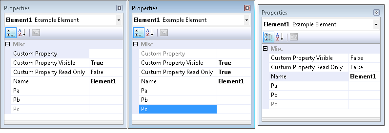
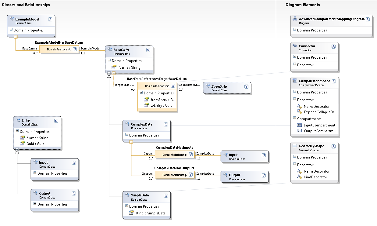
The ExampleModel has three properties (P1, P2, P3) and in the original DSL Editor these properties are all writable. Properties that are not mentioned by the attributes will work as defined.

If the Restriction Mode is set to RestrictionModes.Advanced two of them are fully assessable (in fact you do not need to create Attributes to set the properties to Restriction.Full since this is the default value) and one is read only. In the RestrictionModes.Simple-case one property will be hidden and two are read only.

You can assign these attribute to each class that shows properties in the Properties Window. That are Model Elements, Shapes, Connectors and the Model itself.

After that you have to create a partial class for your Package and "activate" my library for each Class that uses these attributes:

partial class RestrictPropertiesTestPackage
{
 protected override void Initialize()
 {
  UserRestrictionProvider.RegisterRestrictedElement<ExampleElement>();
  UserRestrictionProvider.RegisterRestrictedElement<ExampleModel>();

  base.Initialize();
 }
}

Or use the shorter way to add all classes with one line of code. This will use reflection to find the classes.

UserRestrictionProvider
 .RegisterAllRestrictedElements
<RestrictPropertiesExampleDiagram>();

Now there is only one step left: how to change the mode. Each Store (that is the class where the Elements of a Model are stored in memory) is mapped to one Restriction Mode. So you can define one mode for each Store and so one mode for each Model or Diagram. The Store can be accessed from each ModelElement, so as a key for this purpose it is a great value. There is a UserRestrictionProvider class with two static methods:

  • public static void SetRestrictionMode(Store store, int mode)
  • public static int GetRestrictionMode(Store store)

You can use these methods whenever you want to change the Restriction Mode. For the demo project I used a Domain Property of the Diagram with Custom Storage.

How does it work?

With the UserRestrictionProvider.RegisterRestrictedElement()method I register a special TypeDescriptionProvider to the global Component Model (via the TypeDescriptor.AddProvider() method). This new Provider is be asked from the IDE whenever a list of all properties of a particular object is needed. At this point it is easy to remove some properties form the original list (this properties are not be shown in the Properties Windows) or make them read only (see the ReadOnlyPropertyDescriptor class in my code).

For more in depth information feel free to take a look at the source code.

…but beware

All these property restrictions effect only the properties windows. The properties can be changed and accessed by code and via other elements of the DSL Designer (for example TextDecorators and the DSL Explorer).

Download

In the zip file you will find all described classes in one project and an example DSL project.

Update

This code is now part of the JaDAL – Just another DSL-Tools Addon Library project. Please download the current version from that page. The download over at CodePlex contains the source code described here, an example DSL language and the library as a binary. Future enhancements of the code will be published there, too.

Finding and removing a default command in DSL Tools (part 4 of Compartment Mappings)

Tags: , , , , ,
2 Comments »

[Update (2008-05-21): This code is now hosted at CodePlex as part of JaDAL. And a follow-up article was published.]

Previously on…

This article is part of a series. A table of contents can be found at the end of the first article. Part 2 contains a user guide and in part 3 I showed most of the internals of the library.

The "Reroute" command

For each connector there is a command named "Reroute" in the context menu of the DSL editor. Now I have to remove this command for the compartment entry mappings. If the user would use it, the layout of my connectors will be destroyed. Unfortunately I did not find an option, an extension point or anything else where I could change or handle this particular command or the context menu of the connectors.

The generated code

First I looked at the generated code of my Dsl and DslPackage project. There is a GeneratedVSCT.vsct file. In vsct files the commands are defined, but in this one I could not find anything with "Reroute". Then I searched for the string "Reroute" in all files and found nothing.

The DSL binaries

I found no documentation for this command and  was a little desperate. I needed to find the place where it comes from. I searched the whole VS SDK folder (text and binary files) for the string "reroute". A promising hint was found in the Microsoft.VisualStudio.Modeling.Sdk.Shell.dll file. Now let’s go to the Reflector and take a deeper look inside.

After a while I found the Microsoft.VisualStudio.Modeling.Shell.CommandSet class. And hey, in the msdn documentation article for this class there is also the Reroute Line command mentioned. With this knowledge one can easily find the generated CommandSet.cs file as part of the DslPackage. In this file there are two classes AbcCommandSetBase and AbcCommandSet where Abc is the name of you DSL project.

The design pattern of this classes is called double derived and can be found quiet often within the generated DSL code. The ...Base class stays abstract and derives from a class defined in the Microsoft Visual Studio SDK libraries, in this case from the CommandSet class I found above. All code created by the code generator is added to this ...Base class. The other class derives from the ...Base class and is empty – all parts of the project uses this one. Since it is declared with the partial keyword, the user can override ALL methods and change the behavior of all aspects of this class.

And that is what we are going to do: override the GetMenuCommands() method and remove the reroute command:

protected override IList<MenuCommand> GetMenuCommands()
{
  // get the base list
  IList<MenuCommand> cmds = base.GetMenuCommands();
  // find the reroute command  
  MenuCommand rerouteCommand = cmds.First(
    c => c.CommandID == CommonModelingCommands.RerouteLine);
  // if found, remove it
  if (rerouteCommand != null)
      cmds.Remove(rerouteCommand); 
  
  // and return the changed list
  return cmds;
}

That’s it. Pretty easy, but you have to discover where to add this logic.

Connectors between compartment shape entries with DSL Tools – part 3

Tags: , , , , ,
3 Comments »

[Update (2008-05-21): This code is now hosted at CodePlex as part of JaDAL. And a follow-up article was published.]

Previously on…

This article is part of a series. The table of contents can be found at the end of the first article. In that article you can also find a brief overview. In the second part there is a short user guide and a download link of the source code and binaries.

How does it all work?

I don’t want to explain every single detail of my code. If you want to go that deep, you have to read the source code yourself and maybe you will find some comments. I will only show you the fundamental parts of the CompartmentMapping library.

There are a few things you have to consider to achieve the aim of the library:

  1. When creating a connector from Shape A to Shape B how should I get and store the Compartment Entry information for the Reference Relationship?
  2. After that, the connector representing this relationship must be drawn in such a way that it seems to be a connector from one entry to another.
  3. What can a user do to destroy the layout of my connectors? And even more important: how can I prevent him from doing so?
  4. If the user deletes a compartment entry that is part of a relationship, the relationship needs to be deleted, too.

The Connection Builder

There is the concept of Connection Builders used by the DSL Tools. While your day to day use of DSL, you don’t have to worry about Connection Builders since they will be generated by the DSL Tools code generator. But you can turn this generation off and provide your implementation of a Connection Builder for a certain relationship. (see number 5 in the user guide).

A Connection Builder is a static class and will be assigned to a connection toolbar item of your editor. This class contains four interesting methods:

  1. bool CanAcceptSource(ModelElement)
  2. bool CanAcceptTarget(ModelElement)
  3. bool CanAcceptSourceAndTarget(ModelElement, ModelElement)
  4. ElementLink Connect(ModelElement, ModelElement)

The first two methods are used to determine if a particular ModelElement can act as source or target of you connection. For example you can check the ModelElement for a certain property to be set and only allow elements with this property as source and with another property as target, or whatever.

With  CanAcceptSourceAndTarget() you can check whenever a concrete combination of source and target ModelElements is allowed to be connected by your relationship.

Last but not least with the Connect() method you have to create this new relationship for the two selected ModelElements.

In such a Connection Builder I will add the logic to check not only the model elements but also the selected entry inside the Compartment Shape. At this point I will mix the model representation (containing of Domain Classes and Relationships) and the graphical appearance (containing of Shapes and Connectors) but there is no better way at this time since the DSL Tools can only create connectors from shape to shape.

The first problem I ran into: How to get the shape of the model element in the Connection Builder if the only parameter is the ModelElement? I used the PresentationViewsSubject.GetPresentation() method and I’m hoping it will always work. The architecture is build in such a way, that one ModelElement can have multiple shapes, but I didn’t saw such a configuration until now, so I assume there will be only one shape.

After holding the shape in my hand I need to know something about the selected Compartment Entry. This becomes a little bit complicated, too: Sometimes I need the entry right below the mouse cursor (for CanAcceptSource()) and sometimes the entry that was below the mouse when the user pressed the mouse button. Of course a Compartment Shape doesn’t provide any of that information. Take a look at CompartmentMouseTrack and ICompartmentMouseActionTrackable in the CompartmentMapping library and you will see in which way I handle mouse events of the shape to track all these mouse actions for the Compartment Shapes that are under the control of my library.

With all these new information my CompartmentMappingBuilderBase can decide to allow or permit the creation of a connection. With some virtual methods, it can delegate  more details of this decision to your code (see the advanced options here).

How to trick the routing algorithm of DSL Tools

With the Connection Builder one can create relationships in the domain model but the connector inside the visual representation of your model will still be routed from shape to shape and won’t give you a proper understanding of the entry to entry relationship. So we have to change the routing in a way that the start and endpoints of the connector will be glued near to the entry on one side of the shape.

This will be done with an AddRule (CompartmentMappingAddRuleBase) every time a new connector will be added to the diagram (and when opening a saved diagram).

After determination the favored points on the shape outline you can set them to the connector with the FromEndPoint and ToEndPoint properties. Don’t forget to change the FixedFrom and FixedTo to VGFixedCode.Caller as well.

Don’t get tricked by the routing algorithm

If you change the start and endpoints of a connector in the AddRule these values aren’t set forever.  The user could collapse and expand the compartment shape or use the "Reroute" command that is visible in the context menu of every connector. He could also move the connector or only the start and endpoints on the shape outline. If he deletes one entry that was shown above an entry with a connection this entry moves closer to the top and the connection should do the same.

With a few lines of code, we can forbid the user to change the routing of a connectors. In the connector class the CanManuallyRoute property simply have to return false.

Every time the size of the shape changes (see OnAbsoluteBoundsChanged event) I will recalculate the connection points of all connectors assigned to this shape. This event will handle a bunch of cases for me: insertion and deletion of other entries, expanding and collapsing of the whole shape and singe compartment lists and renaming of entries which can cause reordering of the compartment list.

Delete propagation

The delete propagation is an easy requirement. I just added a DeletingRule that keep track of the deletion of certain Compartment Entries and if one is deleted it looks for Compartment Mapping Relationships and deletes them.

It is a little bit challenging to find the relationships coming from the entry. If you want to know more details take a look at the CompartmentEntryDeletingRuleBase source code.

Upcoming article

In the last article of this series I will explain the way of removing the "Reroute" command from the connector context menu. The actual code consist only of a few lines, but the way I found the point to do it can be interesting for someone because the "Reroute" command is not proper documented anywhere.

Connectors between compartment shape entries with DSL Tools – part 2

Tags: , , , , ,
7 Comments »

[Update (2008-05-21): This code is now hosted at CodePlex as part of JaDAL. And a follow-up article was published.]

Previously on…

This article is part of a series. A table of contents can be found at the end of the first article. In that article you can also find a brief overview.

    User guide

    If you read this article to this point you will properly use or at least evaluate the CompartmentMapping library. I will provide you with a step-by-step tutorial. There are pretty some steps, but its the shortest way I could imagine to create my solution. Please give it a try. 🙂

    1. You need TTxGen to generate some code from my templates. See my last article for more information and a workaround for an installation problem.
    2. I assume you have a DSL solution and at least two Domain Classes mapped to two compartment shapes and two more Domain Classes used as entries of the compartment shapes created. In my example these classes are called Parent1, Entry1, Parent2 and Entry2.
      The entries need a unique identifier. You could use a name property for this, but there will be some difficulties if the user creates two entries in one shape with the same name, so I will use a guid. (Don’t forget to create a new guid in the constructor or another proper place.)
    3. Create a Reference Relationship from Parent1 to Parent2. This will be automatically named Parent1ReferencesParent2. We will use this reference to present the relationship from one entry to the other. I would like to create Reference Relationships from this relationship to the entries, but relationships of relationships are not supported. We have to store the guids of the entries in the relationship and add two Domain Properties for this purpose to it. I named them fromEntry and toEntry.
      DslDefinition 
    4. Set the Allows Duplicates property of the Parent1ReferencesParent2 relationship to true.
    5. Set the Is Custom property of the Connection Builder (Parent1ReferencesParent2Builder) in the DSL Explorer to true.
    6. Add a reference to CompartmentMapping.dll to both the Dsl and DslPackage project.
    7. Add a new xml file (in my example CompartmentMappings.xml) to your solution and write the following code in it:
      <?xml version="1.0" encoding="utf-8" ?>
      <CompartmentConnections
          xmlns:xsi="http://www.w3.org/2001/XMLSchema-instance"
          xsi:noNamespaceSchemaLocation="CompartmentMappings.xsd"
          namespace="BenjaminSchroeter.CompartmentMappingExample" >
        <CompartmentConnection>
          <CompartmentSource>
            <DomainClass name="Parent1"/>
            <EntryDomainClass name="Entry1"/>
            <Shape name="CompartmentShape1" />
          </CompartmentSource>
          <CompartmentTarget>
            <DomainClass name="Parent2" />
            <EntryDomainClass name="Entry2" />
            <Shape name="CompartmentShape2" />
          </CompartmentTarget>
          <Connection name="Parent1ReferencesParent2">
            <Shape name="Connector" />
          </Connection>
        </CompartmentConnection>
      </CompartmentConnections>

      (If you place the xsd file in the same directory you get IntelliSense and error checking for free.)

    8. Place the CompartmentConnections.tt file in the same directory and right-click on the xml file and choose Generate xGen Template. A CompartmentMappings_xGen.tt file will be created below the xml file and there you have to add the following lines:
      <#@ ParentFileInjector processor="TTxGenDirectiveProcessor" 
          requires="fileName='CompartmentMappings.xml'" #>
      <#@ include file="CompartmentConnections.tt" #>

      (Be sure you use the right xml file name here.)

      Now press the Transform All Templates Button in the Solution Explorer to generate the the code from this template.

    9. Now you have to write code by yourself (nearly by yourself, the frames are generated, too). Take a look at the generated cs file CompartmentConnections_xGen.cs.

      At the top you will find commented code. Copy this code to a new cs file and remove the comments. All code you will write for the compartment mappings you will write in this file.

    10. Complete the CreateElementLink() method in this file. Here you have to add code to store the selected compartment entries for source and target in the properties of the relationship (see 3).
      protected override ElementLink CreateElementLink(Parent1 source,
        SelectedCompartmentPartType sourcePartType,
        Entry1 sourceEntry,
        Parent2 target,
        SelectedCompartmentPartType targetPartType,
        Entry2 targetEntry)
      {
          Parent1ReferencesParent2 result = 
              new Parent1ReferencesParent2(source, target);
          result.fromEntry = sourceEntry.Guid;
          result.toEntry = targetEntry.Guid;
          return result;
      }
    11. In the CreateElementLink() method you have stored the source and target entry information somewhere; my library does not know about this location. So we need two more methods to compare an entry with a relationship and answer the question "Is this entry the source of a given relationship?" and the same for the target. These code resists in the same file:
      public override bool IsEntryConnectionSource
          (Entry1 entry, Parent1ReferencesParent2 connection)
      {
          if (entry == null)
              return false;
          return connection.fromEntry.Equals(entry.Guid);
      }
      public override bool IsEntryConnectionTarget
          (Entry2 entry, Parent1ReferencesParent2 connection)
      {
          if (entry == null)
              return false;
          return connection.toEntry.Equals(entry.Guid);
      }

      Always care for entry == null this will be used to check whether the head of the shape is meant. Even if you do not allow the head as source or target this method will be called with a null parameter from time to time.

    12. Create a partial class for your Domain Model (CompartmentMappingExampleDomainModel) and add the following methods.
      protected override Type[] GetCustomDomainModelTypes()
      {
        return CompartmentMappingUtil.AllCompartmentMappingRules(this);
      }

      (If you have already some custom rules, you can use an overloaded version of the AllCompartmentMappingRules() method.)

    13. In the DslPackage project create a partial class for the generated Command Set and add the following code:

      protected override IList<MenuCommand> GetMenuCommands()
      {
          return CompartmentMappingUtil.RemoveRerouteCommand
                                      (base.GetMenuCommands());
      }

    That’s all. Only 13 steps, a few settings and conventions and 10 lines of C# code to write. I know it is not very easy but I think it is ok. And the best: as you will see it is working.

    Now compile and start you solution. You can now create connectors from one entry of the Parent1 shape to an entry of the Parent2 shape. Great – isn’t it?

    mapping 

    Take a look at the properties in the Properties window when selecting a connector. You see the guids of the corresponding entries and can use them in your code when working with this connections for code generation or whatever you need to do.

    Advanced options

    There are some more options besides the basics described above to configure and extend the compartment mappings.

    Some of them can easily turned on in the xml file:

    • For CompartmentSource and CompartmentTarget you can specify an attribute called allowHeadAsSource (and allowHeadAsTarget respectively) and set it to true, to allow the head of the compartment shape as source or target. Remember, if you do this the CreateElementLink() method will be called with null values for the entries and you have to handle this.
    • On the Connection element there are two more optional attributes, too.

      If you set allowSelfReference to true the user can create connections from one entry of one shape to another (or the same) entry of the same shape (source = target). This makes only sense if you specify CompartmentSource and CompartmentTarget to be the same Domain Class and the same shape.

      With the suppressEntryDeletePropagation attribute set to true you suppress the deletion of the connection when a corresponding compartment entry is deleted. Be careful with this setting: Wrong connections will remain in your model and produce ugly diagrams.

    • One of source and target can be a regular shape (that is a geometry or image shape and not a compartment shape). Replace either CompartmentSource with Source or CompartmentTarget with Target. For these elements you don’t need to define a EntryDomainClass element since regular shapes do not have entries.

    You can add even more code to the C# file from step 9 to 11. There are two more methods you can override: CanAcceptAsCompartmentSource() and CanAcceptAsCompartmentSourceAndTarget(). If you do so, the DSL editor will ask your code while the user moves the mouse over shapes when creating the connection to identify the current shape and entry as a valid source or target in you scenario. It is pretty much the same pattern as used in the DSL Tools itself. But remember, this method will be called very often und should have a very short running time.

    Download

    The archive contains the library both as a compiled dll and as source code and the Example DSL created in this article.

    Update

    This code is now part of the JaDAL – Just another DSL-Tools Addon Library project. Please download the current version from that page. The download over at CodePlex contains the source code described here, an example DSL language and the library as a binary. Future enhancements of the code will be published there, too.

    Upcoming articles

    Part 3 and part 4 of this series will give an in depth view into the internals of the library.

    WP Theme & Icons by N.Design Studio
    Entries RSS Comments RSS Log in