How to catch SqlExceptions and don’t get into trouble about aborted transactions by SQL Server (or: how is it possible that a transaction is only executed halfway)

Tags: , , , ,
No Comments »

We witnessed a strange behavior in one of our projects that caused me some headache. Unfortunately, we could only observe it in production environment and never reproduce it. I took a look at the databases and could not imagine any circumstances that lead to such data. One day I said:

It looks like the transaction was only executed halfway or like a broken rollback.

But we were using Microsoft SQL Server and I could not imagine the existence of a bug that does such a thing and wasn’t already fixed to the current version.

By luck I got a clue and I could fix it in our code. Here is what happened:

The database

For the sake of simplicity let’s use this database with just two tables:

  • Table Data
    • Id (PK, int, not null)
    • Data (varchar(50), not null)
  • Table Log
    • Id (PK, uniqueidentifier, not null, autovalue)
    • Text (varchar(max), not null)

The code

try
{
 using (var transaction = new TransactionScope(TransactionScopeOption.Required))
 using (var connection = new SqlConnection(ConnectionString)) 
 {
 connection.Open();
    var insertDataCmd = connection.CreateCommand();
    insertDataCmd.CommandText = "INSERT INTO Data(Id, Data) VALUES(1, 'Foo')";
    try
    {
          insertDataCmd.ExecuteNonQuery();
    }
    catch (SqlException e)
    {
         Console.WriteLine(e.Message);
         // for some reason i don't care for this PK conflict
     }
    var insertLogCmd = connection.CreateCommand();
    insertLogCmd.CommandText = "INSERT INTO Log(Text) VALUES('this should not find its way to the database')";
    insertLogCmd.ExecuteNonQuery();     
    // don't commit this transaction       transaction.Complete();
 }
}
catch (Exception e)
{
    Console.WriteLine(e.Message);
}


We use TransactionScope to handle transactions. The first INSERT (with Id = 1) will throw an exception since a record with this id already exists. I don’t care about this exception, catch it and go on. Now I insert something into the log table. Finally, I will not commit the transaction at all.

This is a very artificial program to show just one event that has happened.

After running this piece of code I can find a new record in the log table even if the transaction was never committed! – That scared me!

The analysis

The first insert does not only throw a primary-key-already-exists-exception but the SQL Server itself aborted the transaction at this point. The following commands are executed without any transaction or transaction scope at all. I couldn’t imagine that this can happen with that code!

The reason for this behavior of SQL Server was a trigger like this:

CREATE TRIGGER InsteadOfInsertIntoData
 ON [Data]
 INSTEAD OF INSERT
 AS
 BEGIN
   INSERT INTO [Data] (Id, Data)
   SELECT
   Id,
   [Data]
   FROM inserted
 END
 GO

On tables without such a trigger my code works great. I can catch the exception and go on.

With this trigger, the PK error does not raise in user code but within the trigger. If an error happens within a trigger the transaction is always aborted.

(Please don’t start a discussion about this trigger itself. I don’t like it, but it was in the database. Cannot argue about it.)

Maybe with more explicated transaction handling

A colleague pointed out, that TransactionScope may be the problem and I should try explicit transaction handling with the pain old Transaction-class.

try
{
 using (var connection = new SqlConnection(ConnectionString))
 {
   connection.Open();
   var transaction = connection.BeginTransaction();
   var insertDataCmd = connection.CreateCommand();
   insertDataCmd.CommandText = "INSERT INTO Data(Id, Data) VALUES(1, 'Foo')";
   insertDataCmd.Transaction = transaction;
   try
   {
       insertDataCmd.ExecuteNonQuery();
   }
   catch (SqlException e)
   {
       Console.WriteLine(e.Message);
       // for some reason i don't care for this PK conflict
   }
    
    var insertLogCmd = connection.CreateCommand();
    insertLogCmd.CommandText = "INSERT INTO Log(Text) VALUES('this should not find its way to the database')";
    insertLogCmd.Transaction = transaction;
    insertLogCmd.ExecuteNonQuery();
    transaction.Rollback();
  }
}
catch (Exception e)
{
      Console.WriteLine(e.Message);
}

But it does not change much: the INSERT INTO Log got written to the database even with the Rollback() call at the end.


But you can observe something interesting on the transaction instance after SQL Server has aborted the transaction: The transaction-object got a private (!) property names “IsZombied” that got true afterwards. Buts its private, so I cannot access it in my code.

At the same moment the public property Connection of transaction lost its value and got null. A clue one could check but not very explicit and I don’t like to check for such a property every time I want to call ExectuteNonQuery().

A better solution (?)

I figured out that I can dig deeper into the SqlException and check if this exception aborted my transaction:

private static bool WasTransactionAborted(SqlException ex)
{
  foreach (SqlError error in ex.Errors)
  {
     // The statement has been terminated.
     if (error.Number == 3621)
        return true;
  }
  return false;
}

If any of the SqlErrors within the SqlException was of number 3621 then the transaction is dead and I don’t want to run any more code against my SQL Server connection.

The code from above can be changed at the point where I catch (and ignore) the exception to check for the described condition and don’t ignore that one.

 try
 { 
    cmd.ExecuteNonQuery();
 }
 catch (SqlException e) when (WasTransactionAborted(e))
 {
    Console.WriteLine("That's it - sorry - over and out");
    throw;
 }
 catch(SqlException e)
 {
    Console.WriteLine(e.Message);
    // for some reason I don't care for this PK conflict
 }


If the transaction was aborted we re-throw the exception end quit this method. Otherwise I can safely ignore the exception and go on.

Push buttons as input

Tags: , , , ,
No Comments »

imageTo control the lights in a house or in my own apartment switches and buttons near the doors in the wall are a very useful thing.

Even if my home automation can be controlled by ethernet, mobile phone, timers, you name it, it will be most convenient to use normal switches, too. I was lucky to rewire the whole apartment and I decided to  put a separate wire for each switch to a central place where my home automation controller will be placed.

I will use push buttons instead of on/off-switches. Push buttons can be used for multiple commands. Starting with turning a light on or off, you can program it to do different actions when pressing just for a short or a longer time. Or you can do a continues action as long as the button is pressed down.

But first of all the signal from the buttons needs to be received by my micro controller. I will use 12V DC for all buttons, to avoid higher power like 110V or 220V AC. To protect the electronics and don’t get trouble with long wires at all I use optocouplers. Basically the 12V from the push button just turns on a small LED within the optocoupler from where the signal takes its way.

The schematics

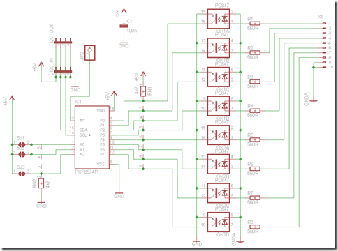
The signals itself are received by a PCF8574 I/O-chip. This chip comes with 8 digital I/O ports and an I2C interface. The microcontroller can query the state of all I/O ports using the I2C interface. As a bonus the chip triggers an interrupt each time any input signal is changed.

digitalin

There is nothing fancy at the schematics, just read it from right to left. At the very right you will find 8 inputs for the 12 V from my pushbuttons (and the GND used with this signal). Following by the optocouplers. To use more or less then 12 V just adjust the resistors value. The rest of the schemantics are just pull up and down resistors and some more connectors for the I2C bus.
The board will be build in a way to chain multiple of this boards together. The I2C bus goes from one to another.
By using the solder jumpers SJ1, SJ2, SJ3 you can select one out of eight addresses. Each board comes with its own interrupt on connector JP2.

The board

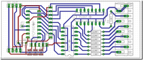
As above you can find the connectors to the push buttons on the right. You will see the two quad optocoupler chips in the middle and the I2C I/O chip at the left.

digitalinbrd

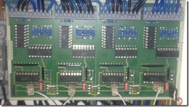
I have four of this boards connected with nearly 32 push buttons. They all share the I2C bus which is connected from one to another (see the small white, red, green and yellow wires at the bottom). But each provides its own interrupt signal. So for the whole installation the microcontroller only needs four IRQ ports and one I2C bus.

IMG_3111_crop

The code

Will be the topic of my next post. Stay tuned.

What is this all about

If you find this post interesting, have a look at the other posts in my homeautomation category within this blog. Especially the first and the second post describe what this is all about.

The schematics and boards (created with EAGLE) and all source code is or will be available on github: https://github.com/irgendwienet/homeautomation

Power, I2C and DMX

Tags: , , , , ,
No Comments »

The first board for my home automation project needs to provide everybody with Power (5V DC). This is the main purpose of this board and because this is a very basic requirement it’s the first to be described here.

But this board handles two more jobs:

  1. create 5V DC from input voltage of 12V DC
  2. convert a 3,3V I2C bus to an I2C bus capable of speaking with 5V components
  3. driver for the DMX signals

Power

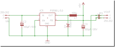
Here’s nothing special. Just a P3596L-5.0 step-down DC/DC converter, two capacitors, an inductor and a diode.

06-01-2013 13-32-58

I2C

The microcontroller I’m using only has 3,3V output pins even if they are 5V tolerant you cannot connect 5V I2C components. But the rest of my setup is build with 5V components so I have so power up the I2C-Bus accordingly.

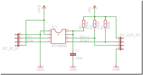
Luckily there is a chip that does the exact same thing: the PCA9306 a dual bidirectional I2C bus voltage-level translator.

It just needs a 3,3V (I get this directly from the microcontroller board) and 5V current and the input I2C bus. No big deal at all.

06-01-2013 13-59-50

DMX

DMX is a protocol used on stages for controlling lights. I use the same for dimming my LEDs in the whole apartment. Today I will not go in much details about the protocol or the software side.

On the wire DMX is just a symmetric RS-485 signal on three wires (called + / – / GND).

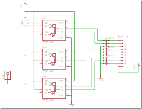
I use a simple SN75176 differential bus transceiver chip but since DMX is only sending in one direction there is no need in using the receiving side of the chip. The control ports are hard wired for sending and it gets its signal from an UART of my microcontroller.

On my board I put three of the same chips to create three physical separated busses with the same signal.

Again, here is less magic involved:

06-01-2013 14-06-32

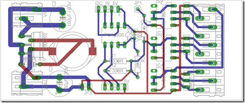
The Board

06-01-2013 14-07-25

From left to right: Power / I2C / DMX

What is this all about

If you find this post interesting, have a look at the other posts in my homeautomation category within this blog. Especially the first and the second post describe what this is all about.

The schematics and boards (created with EAGLE) and all source code is or will be available on github: https://github.com/irgendwienet/homeautomation

State of the art: my home automation

Tags: , , ,
2 Comments »

It has been a long time since my first post about home automation in my new apartment. And now it’s time for a wrap up what’s going on here. First of all: most what is described in that post is implemented and up and running for more then one year now.

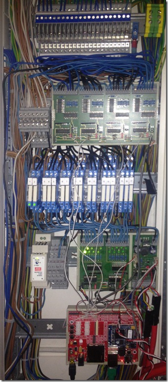
So let’s have a look at the basic setup that’s in my closet:

IMG_3098crop

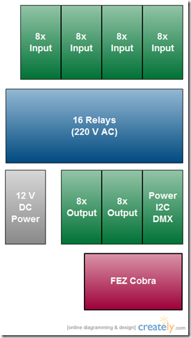
Or as an easy to read schematic:

diy

At the bottom you find the FEZ Cobra board. That’s the µC-board or the heart of everything here.

In the row above a simple 12 V power supply can be found, two cards of output drivers for the relays and a card with multiple purpose: Power regulator, I2C voltage converter, DMX driver.

The blue rows contains 16 relays switching 220 V DC lights within my apartment. This is the only part of my whole installation where the power is more then 12 V. So be careful when touching here.

At the top row four cards with each 8 input ports with optocouplers can be found.

I will describe all parts in futures posts in detail.

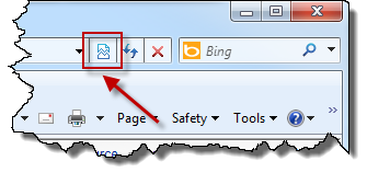
Accessing git repositories with hg (mercurial) tools

Tags: , , , ,
No Comments »

Preface

Once upon a time we switched from subversion to Mercurial (or hg) as source control system. We choose hg because at that time the tool support on windows was much better for mercurial as for git. Not all of us wanted to go the console-only approach and I still love my TortoiseHg very much. We are very happy with our hg setup and have no intension to move away from it.

But from time to time I come across a git repository I want to clone or I have to collaborate with somebody else on a git repository. Soon I’m planning to release a project on github since this is currently the community to go if you want to publish your stuff. But still I would like to stick with only a small set of tools.

The Hg-Git Mercurial Plugin

Instead of getting git to my machine (in fact it is running here anyway) I found the Hg-Git Mercurial Plugin. This allows you to use hg on your local box but pull and push to a git repository.

On first sight it works pretty nice but I had some challenges to overcome when installing it. And that’s what this post will be about.

Installing the Plugin

The homepage of the Plugin itself can be found at http://hg-git.github.com/ with the source code available at github and bitbucket.

Even with easy_install available on my windows machine I could not install the plugin as described at “Installing Hg-Git the easy way” but the other way “Installing Hg-Git manually” is not much work at all. Dulwich was installed when I tried the easy way before, so I only had to get the code and edit the hg config file.

Get authentication working with github

For each repository over at github the SSH url is shown at the website like
git@github.com:irgendwienet/testing.git

To use this with your hg installation just prefix it with git+ssh:// like
git+ssh://git@github.com:irgendwienet/testing.git

But then a “PuTTY Fatal Error” in a message box pops up “Disconnected: No supported authentication methods available (server sent: publickey)”

So you have to do two things: upload your public ssh key to github and explain your local system to connect using your private key.

To upload a public key just log into github, go to Account Settings and into the SSH Keys section.

Then open putty.exe and configure the following:

  • Host Name = github.com
  • Connection / SSH / Auth / Private key file for authentication = your key file

Save this session as “github” (the name will be imported during the next step).

Now try cloning the repository again but instead of the actual URL (github.com) use the name of the session (just “github” in my case). Putty looks for this session and finds the actual URL with the key.
git+ssh://git@github:irgendwienet/testing.git

Do it yourself: home automation

Tags: , , , ,
7 Comments »

For my new apartment I imagine some nice (or nerdy) infrastructure things. Since the apartment is currently building and I can decide how to do the wiring: we will get CAT7 Ethernet nearly everywhere for gigabit Ethernet. We will get a lot of power outlets, HDMI cables from the stereo to the TV and to a potential place for a projector and so on.

I was also looking into systems for home automation to control lights etc. using some commercial bus system like KNX. But all these systems are boring, expensive, inflexible and absolutely not the kind of system I was willing to invest a few thousand euros in. They advertise all that stuff as programmable and ultra flexible. But you need some expensive software and special adapters to reprogram your house. To save light configuration and recall them by a button you need some light-configuration-controller-hardware (at about 200 Euro) and a guy to program it. Non of the classical home automation systems can be controlled with an iPad.

So I decided to build something for my apartment by myself. In this first post of many I will show you my basic ideas and later I’m planning to publish hardware schematic and software source code for single modules and maybe for the whole thing.

The goal

  • Control every light in every room of my apartment
    • some will just turn on / off
    • some are dimmable
  • Controlled by the regular light switches
  • A “Turn everything off” switch at the main door
  • Connected to my local network (e.g. webservice)
  • My personal application on an iPad

optional (or later on):

  • Control the motor for the projection screen
  • Control light by timers
  • Send infrared signals to the stereo and the tv set
  • Connected to the phone line (e.g. turn off the music when the phone rings)
  • Receive data from wireless sensors
  • Add a sensor to the washing machine and remind me when it’s finished
  • much more

The basic concept

To control all this I will use some central microcontroller in my apartment. I decided to give the Microsoft Micro Framework a try. Since I’m already a .Net guy it should be pretty easy (and cool) to program my home in C#. I will use the FEZ Cobra board. A 72 MHz ARM device with 12 MB RAM. It is probably already too powerful for my usage but who cares. It comes with USB-Ports where you can connect keyboards, joysticks or cameras. It has a build in Ethernet port, a SD-Card slot a lot of I/O Ports and everything else you need. One could also connect a TFT touch screen. With this guy I have all the connectability I need and enough power to implement all crazy ideas in software.

In the walls I will get push buttons instead of regular on/off switches and a single cable will be used for each of this button to a central place where my project resists. This way the Cobra board can receive signals from all buttons.

To control the lights the cables will be put to these place too. Here I will use relais or dimmers controlled by the Cobra board. For some lights I will try RGB LEDs with DMX controllers (I will later explain what that exactly is).

A little bit more in detail

The key to all this is my custom wiring with a lot of more cables in the walls then usually. Since the apartment will be newly build I can get this wiring without big problems.

My push buttons will be powered only by 12V or 24V DC not 240V AC (the normal power in Europe). This way it is much easier to connect it to the Cobra board.

For controlling dimmers I will use dimmers with a control input of 0 to 10V. Again: it’s much easier to buy some working and proofed dimmers for the 240V high voltage and my DIY projects only controls it by a 10V signal. The same for switches: the Cobra board will drive some relais with 12V DC and the relais will switch the 240V AC line.

Maybe I will use for dimmers and other light controlling stuff the digital DMX512 protocol. This is used on stages to control all the light effects and seems pretty simple to implement on the hardware and software side.

For most of these functions I will create small hardware modules and connect them to the Cobra board. This way the completion of the whole project is much easier. Some of these modules will be connected to the I/O ports of the Cobra directly and some will use a I2C-Bus.

Some modules first

To get stared I created hardware prototypes for the first modules of the system. These modules can be used for the purpose I’m planning or for something totally different (at the end these are only input and output port controlled by a microcontroller). I will show you the different modules in upcoming posts. Once finished the major parts I believe I will extend the whole system step by step. But let’s start with:

  • I2C voltage converter
    • since the Cobra board uses 3,3V but all other modules will use 5V I need a simple voltage converter
  • I2C input module for push buttons
    • using optocouplers and an I2C-I/O-chip
  • I2C digital output modules
    • with an I2C-I/O-chip again and some drivers to power relais
  • I2C analog outputs
    • to create the control voltage for 0-10V dimmers.
  • DMX512 output


Within the next weeks I will start to write a post to each of these modules with detailed hardware and software explanations.

Cannot access VMware Server Web Access

Tags:
No Comments »

I’m running a VMware Server 2 on a Linux box and access this service via the VMware Server Web Interface at https://server-name:8333. This is a pretty usual way of interacting with VMware Server.

But suddenly I cannot access the website any more. Internet Explorer just said “Loading…” forever but nothing happened.

If the same happened to you try to switch Internet Explorer into Compatibility View and it may work again (it did on my machine).

a

Be careful with certain ctors of XmlSerializer

Tags: , ,
No Comments »

In my current project we’re using XmlSerializer a lot. At some point I need to write about 400 files with the XmlSerializer. For some reason I created a new XmlSerializer for each of these files.

I discovered during debugging a lot of debug messages in Visual Studio output window like:

'Application.vshost.exe' (Managed (v4.0.30319)): Loaded 'm0dayvr5'
'Application.vshost.exe' (Managed (v4.0.30319)): Loaded 'oxxqw1rq'
'Application.vshost.exe' (Managed (v4.0.30319)): Loaded 'dgh3mgtl'
'Application.vshost.exe' (Managed (v4.0.30319)): Loaded '00sdpqlv'
'Application.vshost.exe' (Managed (v4.0.30319)): Loaded 'yokpozj4'


Then I remembered that the XmlSerializer creates dynamic assemblies during runtime and loaded them into the AppDomain (and never unloads these assemblies since you cannot unload from an AppDoamin). In the MSDN article I found a solution that explains this behavior:

Dynamically Generated Assemblies

To increase performance, the XML serialization infrastructure dynamically generates assemblies to serialize and deserialize specified types. The infrastructure finds and reuses those assemblies. This behavior occurs only when using the following constructors:

XmlSerializer.XmlSerializer(Type)

XmlSerializer.XmlSerializer(Type, String)

If you use any of the other constructors, multiple versions of the same assembly are generated and never unloaded, which results in a memory leak and poor performance. The easiest solution is to use one of the previously mentioned two constructors. Otherwise, you must cache the assemblies in a Hashtable, as shown in the following example.

Of course you can use any other data structure to do the caching. But you have to do it on your own if you do not use the two mentioned constructors. I’ve got no idea why Microsoft builds caching into the code for some constructors and not for others, but that’s the way it is.

Some performance measurements

I didn’t build a great benchmark, but at least I got a few numbers. Serializing multiple files without caching takes on my machine about 140ms in debug mode and 130ms in release mode. Each time. With caching only the first file takes this 140 / 130ms and every additional file took about 8ms (debug) or 6ms (release).

That’s a speedup of about 17x to 20x!

And you do not produce memory leaks!

PhotoTagStudio 0.7.1 released

Tags: , ,
No Comments »

Today I released the new version of PhotoTagStudio with a very small improvement.

A new option was added to expand the tree of tags at startup.

See http://phototagstudio.irgendwie.net/

Include in VSIX property is missing

Tags: , , ,
No Comments »

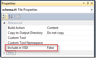
When using the Visual Studio 2010 SDK and creating VSIX packages, you will set for some files the Include in VSIX property within your DslPackage.

I’m not sure what append, maybe it happed on a project I imported from an older Visual Studio version. But for this project the property I needed so much was just missing.

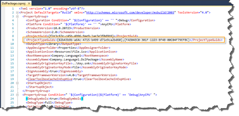
If the same happens to you, you can edit the DslPackage.csproj and add the following line:

<ProjectTypeGuids>{82b43b9b-a64c-4715-b499-d71e9ca2bd60};     {FAE04EC0-301F-11D3-BF4B-00C04F79EFBC}</ProjectTypeGuids>

It worked on my machine and I got this property back.

WP Theme & Icons by N.Design Studio
Entries RSS Comments RSS Log in